
Injection molds rely on a proper guiding system, and the two most important parts of that system are guide pins and guide bushings. These components need careful attention whether you’re buying them off the shelf, designing them in-house, or having them custom-made.
What Are Guide Pins and Bushings in Molds?
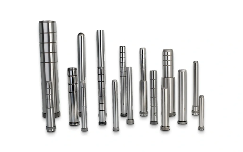
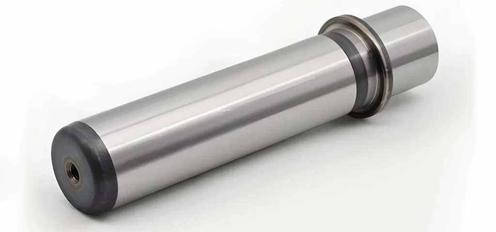
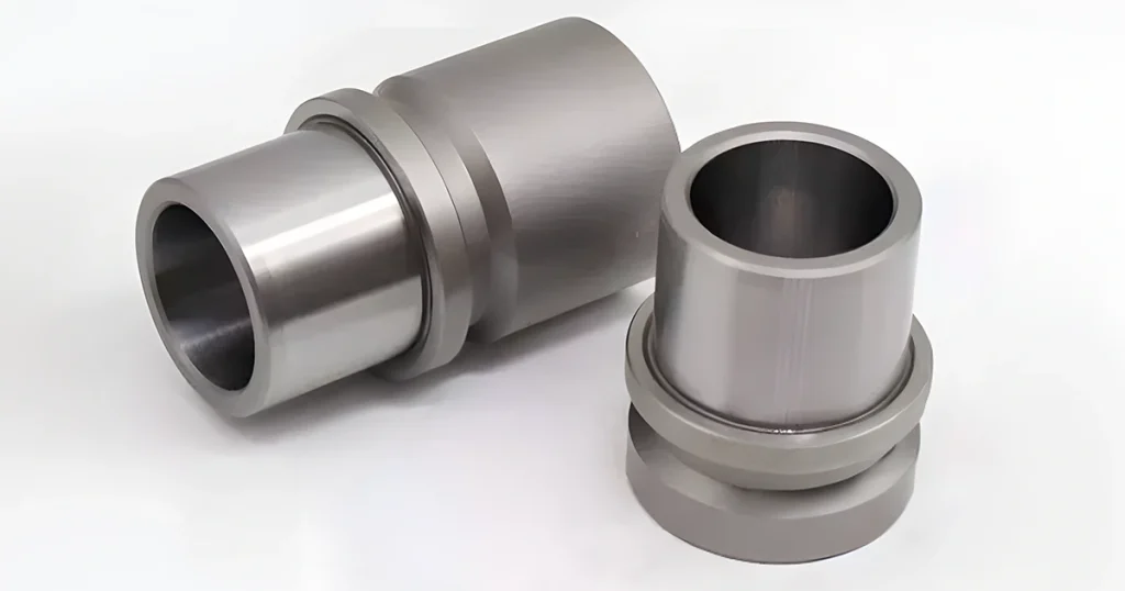
Guide pins and guide bushings are precision fitting components used in mold manufacturing. Their job is positioning and support during processing. Guide pins are usually long, cylindrical (or sometimes square) parts, while bushings are the sleeves they slide into.
Fitting Methods
There are several ways to fit guide pins and bushings together, but the two most common are clearance fit and interference fit. Clearance fit leaves a small gap between the two parts, which helps reduce deformation from thermal expansion and contraction. Interference fit, on the other hand, presses them together tightly for more rigid support and positioning.
What They Do
Two main functions: positioning and stability. Through precise machining and matching, they make sure everything lines up correctly. And when the mold vibrates or gets knocked around during operation, the fit between the pin and bushing keeps things stable so machining accuracy doesn’t suffer.
Types of Guide Pins and Bushings
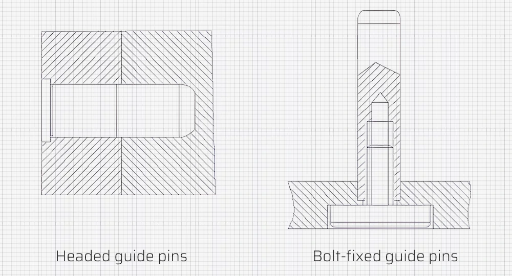
The most common guide pins are headed guide pins and bolt-fixed guide pins.
Bushings come in a few varieties too:
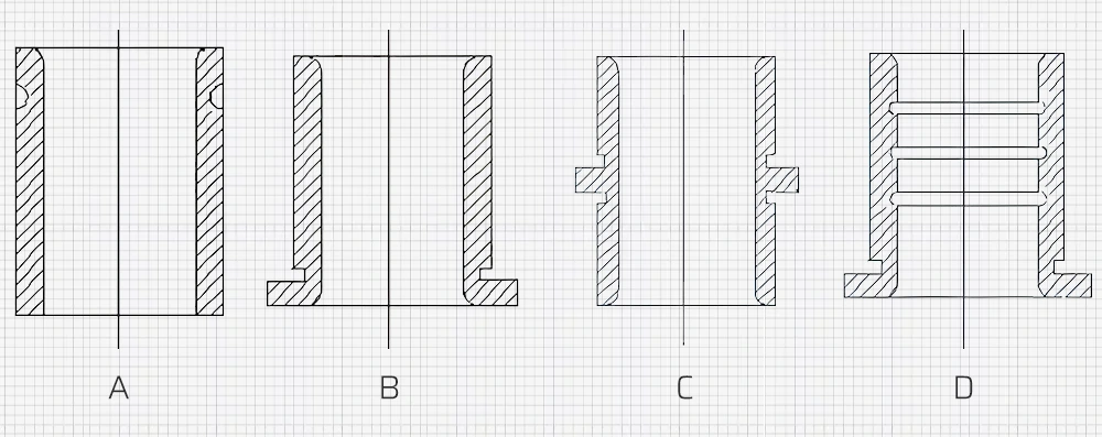
- Straight bushing (a): Used where the guiding hole needs to be short or the template is too thick.
- Riveted head bushing (b): The end is riveted to stop the bushing from being pulled out by the guide pin.
- Headed bushing (c): Used when the template thickness isn’t enough to meet the guiding hole length requirement. Installed with a looser fit than the primary template.
- Grooved bushing (d): Reduces friction when the diameter gets large.
Layout in Mold Design
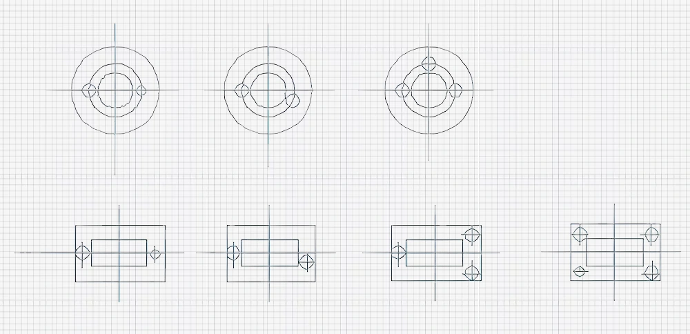
A typical mold has 2 to 4 guide pins. Small or portable molds usually get 2. Medium to large molds get 3 or 4, with 4 being the standard configuration.
To make sure the mold closes in only one correct direction, we usually arrange them in two ways:
- Symmetrical layout, but one guide pin has a different diameter.
- Asymmetrical layout, same diameters but one pin is placed off-center.
For stable guidance, keep the guide pins spaced as far apart as practical, usually outside the cavity. The distance from the guide hole wall to the template edge should be a little bigger than the guide pin radius.
Sourcing Guide Pins and Bushings
Buying from Suppliers
Most mold manufacturers buy guide pins and bushings as standard parts. It saves time and lets us focus on what really matters — machining the cavities and inserts. China’s supply chain for mold components is mature and affordable, so external sourcing makes sense for most shops.
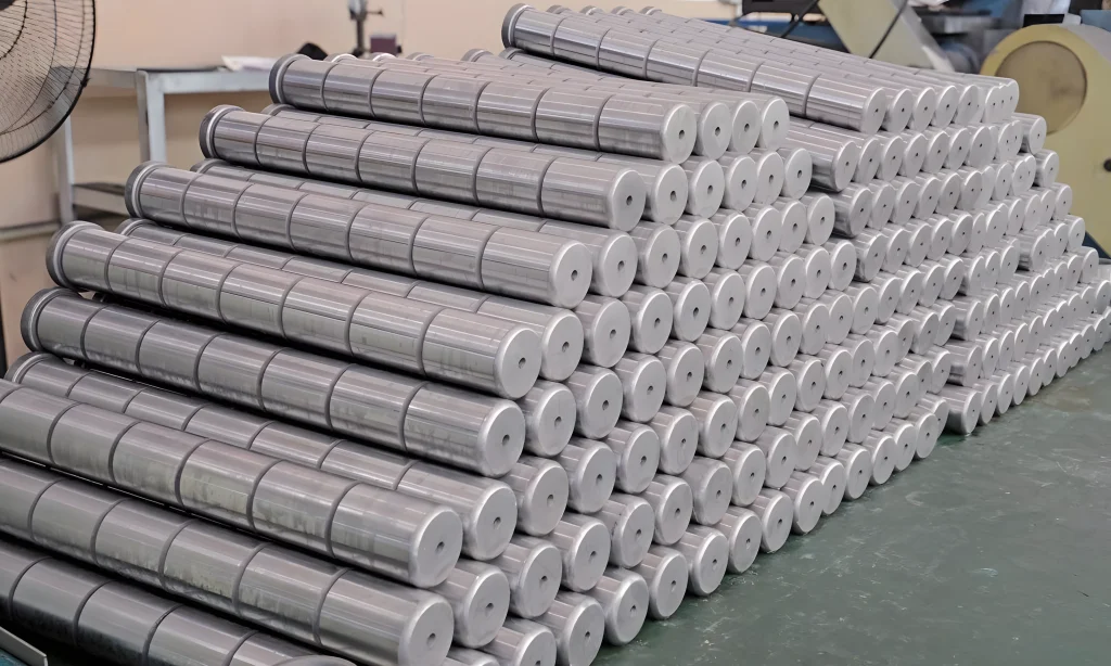
When buying from suppliers, pay attention to:
- Quality: Dimensional stability, surface finish, and material consistency.
- Service life: How many cycles the components can handle before wearing out.
- Ease of maintenance: How simple they are to service and replace.
- Maintenance costs: Frequency and cost of upkeep.
Making Them In-House
For shops that prefer to make their own, guide pins are typically machined from 20 steel. The process goes: rough turning on a lathe, heat treatment (carburizing to 0.8-1.2mm depth, hardened to 58-62HRC), then external grinding. For tighter tolerances, leave a 0.01-0.015mm margin and do additional grinding.
Bushings are similar: rough turning with a 0.3mm grinding margin, heat treatment (same carburizing specs), then internal and external grinding. Since the pin and bushing need high coaxiality, we usually grind the inside first, then fit it on a mandrel for external grinding.
Custom Ordering Guide Pins and Bushings
When you order custom guide pins and bushings, keep these factors in mind:
Material selection: Carbon steel, alloy steel, or stainless steel. Pick based on the working environment, hardness, wear resistance, and corrosion resistance needed.
Dimensional precision: Stick to the print tolerances exactly. High precision is non-negotiable for proper fit and assembly.
Machining precision: The fit quality and service life depend directly on how precisely these parts are made, especially in electronics and optics applications.
Surface quality: Good surface finish extends life. Surface treatments should prevent corrosion and damage.
Lubrication: Use proper mold lubricants — special non-seepage
types are best for long-term durability.
Maintenance: Regular cleaning and lubrication keep everything running smoothly.
Assembly Guidelines
During design and assembly, the guide pins and bushings must fully close before the punch contacts the workpiece. Leave a 10-15mm gap between the top of the guide pin and the upper mold base surface. After assembly, keep a 2-3mm gap between the guide pin and the lower mold base surface, and between the bushing top end and the upper mold base surface.
For symmetrical workpieces, use different diameters or offset positions for the guide pins to prevent directional assembly errors. If there’s large lateral pressure, add thrust pads so the pins and bushings don’t have to take those side forces. And don’t forget vent holes on the bushings to release trapped air.
